This is a new take on an old design. This author read a article couple of years ago in January 2010 QST magazine about this antenna and the success that author had. I had to build one to see for my self. what I discovered in building this antenna is there are many varying factors that will lead to a success or a failure. Those factors are the type of coax used to feed the antenna, the element spacing and the double boom spacing.
The idea behind the Log periodic Dipole array(LPDA) is very simple. The antenna is driven from the end elements, and the mast. the mast or boom is separated and insulated from each other. Thus. the coax is connected with the center lead to one side and the shield to the other side of the antenna.
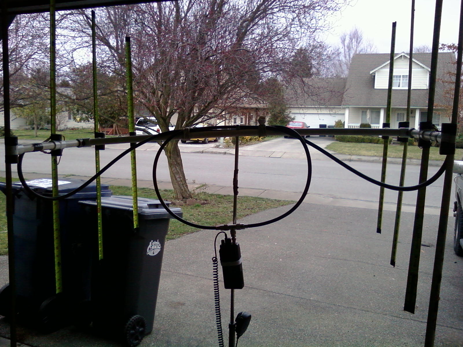
This 4 element LPDA being built entirely out of aluminum, is very portable and light weight. it is also very directional and has a high gain.
The Feed line variable;
You will want to feed with RG-58 U coax in an odd multiple of 1/4 wave lengths of 2meters. feeding the antenna in this manner it has a broad band coverage of 1.3:1 at 140 MHZ to 1.2:1 at 150 MHZ with a dip of 1:1 at 144 to 146 MHZ. This author discovered that using RG-8U or the mini 8 coax caused undesirable readings and performance.
Construction ;
the antenna boom is constructed of two (2) pieces of 3/4" aluminum angle cut at a length of 23 1/2". starting at one end you can mark holes for drilling a 1/4" hole in both angles. You can clamp both angles back to back to drill.
Hole spacings ;
1) 1" from end
2) 4"
3) 8"
4) 12"
These are for your antenna radials to mount to. Now, unclamp your mast and switch it so you can drill through the other half of the angles. put the undrilled sides back to back. This will allow you to drill boom spacing mounts and antenna mounting points.
boom Spacing measured from same end as Radial #1 hole.
1) 6"
2) 18"
Okay now your boom is almost complete. You can begin to assemble it. you will need (8) 1/4"x1/2" bolts, couplers. These are for your antenna radials to mount two.
For your boom spacing, you will need (2) 1/4" x2" nylon screws and (6) 1/4" nylon nuts. start with a boom spacing of 1/2".
For the eight antenna radials, you'll need to cut 1/4" aluminum rod into the following lengths.
4) 19 3/4"
3) 17 3/4"
2) 16 1/4"
1) 16"
Now that you have (8) radials cut you need a way to mount them. on one end of each radial you will need to install 1/4"x20 threads about one inch long. This will allow enough threads to install locking nuts on each radial.
Feed Line installation.
As discussed earlier in this blog, cut an odd length multiple of 2m. Using RG-58U coax. strip and separate about 4" of the coax. I recommend soldering on lug rings that will attach under the #4 couplers. Remember, center lead to one side of boom and shield to the other. I also installed a ferrite core along the coax 6" from the feed point.


 Finally re-installed my radios in my F150 Ford pick up. I wanted to clean up the installation a bit. I used a over head storage/gun shelf I purchased through JC Whitney. I then obtained some light gauge metal the length of the shelf, had it bent. Then with careful measuring I cut openings for my cobra CB radio, Yaesu FT-100D, Z100 auto tuner, and the Bearcat scanner. I also drilled out all mounting holes for brackets and for attaching the metal cover to the shelf. everything is held together with 3/16" fasteners. (nut and bolt combos). all wiring and coax is routed to centralized plug in play on back of shelf hidden from all view.